EDIT: This PDF contains very detailed electrical information for the EEs who wanna go through the complaint: https://www.autoevolution.com/pdf/news_attachements/breaking-nhtsa-petition-shows-tesla-s-sudden-unintended-acceleration-is-real-and-curable-217525.pdf
Last year at /r/RealTesla, a Chinese video of a car rocketing at full speed for 1+ minutes before crashing / killing a pedestrian made the rounds. We all recognized it as one of the weirder cases of “Sudden Unintended Acceleration”, and I think that particular video really changed some minds.
While a lot of SUA events are from driver-error, it began a search into why Teslas seemed to be getting more SUA above-and-beyond the industry normal. This investigation (now filed under NHTSA) suggests that the ADC could be miscalibrated during a load-dump (or other electrical surge-like) scenario.
If the ADC associated with the accelerator pedal is off, then the Tesla will have the pedal at the wrong level of acceleration until the next calibration event, which is not going to happen until over a minute later.
This is extremely similar to that Chinese runaway Tesla, and perfectly seems to explain it. I’m glad that someone seems to have gotten to the bottom of this.
As I mentioned on discord, this is completely nuts and I have some thoughts. First and foremost, when these SUA reports started coming to light, I was entirely convinced that they were cases of pedal misapplication. The angle of the cabin design and position of the drive relative to the pedal box puts you physically in a position where it’s conceivable to me that an inattentive operator would simply press the wrong pedal more often than other brands I’ve driven. This is apparently not the case, and I’ll apologize to every single person I made this argument to. I could have never conceived of such a slapdash design making its way to production vehicles.
Nest, IANAL but I feel like this leaves Tesla open to quite a lot of legal liability. First and foremost the lawsuits Tesla filed against customers for “defamation” can all be called into question at this point. Second, the property damage, injuries, and fatalities all seem like they’d be ripe for any lawyer willing to take on the case. The design is extremely poor in my non-EE opinion and if they could get an expert to testify in court that using an unfiltered 12v reference is a mistake that no engineer should have made, then they seem like they wouldn’t stand a chance. Additionally, any lawyer engaging in discovery over this issue just might find communications from engineering staff to management warning of this issue either during design or testing, if any testing was actually done. If such documents exist, it would demonstrate that Tesla knew of the deficient design and still charged ahead claiming customers were at fault. These all seem like likely scenarios to my non-expert mind.
Finally, the claim that NHTSA was told there wasn’t enough evidence for an investigation and to stop their inquiry is a major misstep by any government agency. Once the crashes started adding up, it seems to me that any inquiry into a deficient electrical or mechanical design was warranted. Especially with some of the speeds measured in these crashes and their locations at such public spots. We’ve seen pharmacies, grocery stores, small shops, large event spaces, arenas, major US intersections, and tiny european streets be the scene of so many of these crashes that I simply can not imagine dismissing an investigation. I don’t know what liability an agency like NHTSA or ODI could face, but this is a pretty serious screw-up on their behalf. It also calls into question whether a larger systems review or analysis will be done against Tesla’s vehicles. It seems like we’re relying on the private sector too much for this work, and I’m concerned there are larger systemic failures lurking under the covers here.
I know we talked about this on Discord but I forgot one key fact.
Tesla has an isolated 12V battery pack already. If the 12V battery pack remained isolated (for cabin / windows / sensors / etc. etc.), then all of this could have been easily avoided.
Tesla vehicles aren’t an ICE vehicle. Tesla has innately separate power supplies for power / steering (aka: the main battery pack), and a separate 12V battery pack for other purposes. This isn’t like ICE cars where the 12V line cannot be physically separated from the alternator or other aspects of the vehicle.
Ok, double comment time. So, reviewing this video: https://www.youtube.com/watch?v=rDYbvI32OBE
At 2:27 he pans across the EPAS module and the BATT1 and BATT2 connectors look exactly the same to me. They are not HVDC cables with the typical bright orange sheath, but rather just red and black. I think this is just two 12v sources. One is likely the DC/DC converter and the other is likely the battery. But for sure there’s no HV connection here and there’s no secondary battery source, it would actually just be that DC/DC converter being called “batt2”.
Odd design, but here we are. I’m positive there’s no secondary 12v source here and that it’s just feeding from “redundant” controller boards and everything feeds through the 12v battery. But I’m just open to the possibility there might be two sources on the body controllers. Again, all would be sourced from the battery and the DC/DC converter would feed through it, but that battery is in the way of all of this and is not actually redundant at all.
There’s certainly two links from BC Front to the EPAS (I keep calling it IPAS for no good reason). And they’re absolutely labeled BATT1 and BATT2. BATT1 is labeled elsewhere in the diagrams as 12v, which I presume means BATT2 means HVDC. But all of the other HV components are called out as HV in some manner, whereas the EPAS just says BATT2. I’m assuming this is tapping the HVDC power in the BC front, though.
Now, having looked at the wiring diagram, I’m wondering something about all the EPAS warning posts we’ve seen on forums over the years. It almost always seems to be related to a faulty ground or a faulty 12v battery connection somewhere, or on rare occasion a dying 12v battery. So now I’m wondering whether the EPAS controller is actually experiencing a fault because of low control circuit voltage or if there’s something else going on here. And if it’s the latter, could it manifest as low supply voltage to the DSP / ADC for the APP sensors?
Ultimately, most of these systems are fused with a FET and current sensors. So you would imagine that Tesla would have detailed logs somewhere in the system about supply voltages and current to all these peripherals. I’d love to see what that data looks like in a scenario where the EPAS warning is triggered, or on a vehicle that’s stationary but receives steering input. Certainly 1.2kW is absolutely nothing to the HV pack, but if it’s going through the same DC/DC that charges the 12v battery, it seems possible that the current could be too high and it could trigger some voltage sag. But the fact that these are all such common circuit designs, I’m just not sure I understand how it went so wrong.
The weasel words are getting to me, honestly.
A lot of the reverse-engineering / hard work seems to have come from the Youtube video, rather than the .pdf / complaint. I think I was confusing who did which work and who was making the arguments.
Fair enough, yeah. I still think the only way this gets any real traction is for a lawyer to hire an engineering team to reproduce this work on the bench and on a vehicle. I’m not sure how you do the latter safely without modifying the boards or modifying the 12v subsystem. Obviously monitoring the +12v bus is easy enough, but the impact of calibration during a low power event would have to be orchestrated carefully.
I need a followup comment post. I cannot believe how huge this PDF is. The alleged evidence is comprehensive and solid.
Page 16 shows the voltage levels of the 12V line (eventually feeding the sensors / microcontrollers ADC) getting wrecked by just… turning left and right with the 1.2kW steering wheel. To be fair, this seems to happen in all cars, but its important to note that the following 12V line is “normal” case of cars.

Given this “changing 12V” situation (as you steer left-to-right and right-to-left), how does this affect the other parts of the Model 3? There’s a lot of analog circuitry going on here, but there’s a few notes.
-
The accelerator pedal is controlled by two voltages. Top voltage is how far down the pedal has been pushed, and the bottom voltage is how far up the pedal has been pushed. (so its a bit redundant for safety reasons, good design here). It takes over 10 pages to fully explain, but just know that there is a safety check, but its not sufficient for #2.
-
The 1.65V reference voltage is affected by the 12V supply voltage. It seems like the 1.65V is inadequately isolated. This means that the 1.65V somehow drops to 0.3V. This has a major effect on the ADC. When the voltage-reference changes voltage, the analog-circuitry in #1 goes haywire… especially if it happens during a calibration event.
Page 19 shows how to replicate this problem and prove the issue with the physical hardware on the Model 3. Pin44 is key on the circuit board.

Messing with the voltage-reference consistently causes the car to think the accelerator is pushed. This is proven in the following table when they miss with that voltage-reference.

So we can see the accelerator pedal at 0% (not pushed at all), but the software of the car pushing the pedal harder-and-harder as this voltage droop over the 12V line gets worse and worse. This is affected at the voltage level, before the signal is even digital or in memory. The voltage conversion itself (aka: the ADC, the analog-digital converter, is busted), so the Tesla logs in the final computer / logs will “prove” that the accelerator was pushed.
But that’s false. The physical pedal was at 0%. Its just a voltage glitch that confused the computer.
…but its important to note that the following 12V line is “normal” case of cars.
This is actually more damning of Tesla, though. The fact this is normal behavior means anybody working in this space should know and would therefore compensate for high and low voltage scenarios. Then consider the fact that the new LiPo 12v battery is only 6.9Ah and you’re basically discharging it at 14.5C to get 100A. The relationship of voltage sag to current draw in a LiPo battery isn’t exactly unknown science. The Model 3 flooded battery is 45 Ah, and claims to have ~ 400 CCA rating. I’m not sure what the sag would look like there, but based on these crashes I bet it’s just as bad.
how does this affect the other parts of the Model 3?
As I mentioned on Discord, if you exposed the FSD computer or even infotainment computer to this kind of huge voltage range, the best outcome would be software crashes because of spurious values in logic circuits. So they clearly knew to compensate for this in the power supplies for these computers. Using simple voltage dividers and op-amps as the reference for the ADCs and then skipping the gain compensation in the DSP is unbelievably lazy.
Worse, IMO, is the fact that TI calls out that you should either design or use a voltage reference generator, of which they offer several compatible with the DSP. Two seconds on the site and I found REF34-Q1 which is an automotive grade component with a cut off voltage of Vout + 50mV. And of course the design guide, data sheet, and other documentation describe how to best use this component in an automotive environment. In other words, this is lazy software and lazy hardware design when there are countless reference designs available.
Of course, the fact that so many systems run from this same 12v line on the inverter boards calls into question how they are properly isolated and protected from such dramatic voltage drops. You’ve got CAN, LIN, the FET drivers, etc. all running off this same rail. When the inverter boards started blowing up, I assumed it was because Tesla wrote a unified firmware for controlling new and old FETs and they were perhaps overdriving some of them and causing them to blow. But now I’m wondering if there isn’t something rooted in hardware causing the issue. If the AC compressor or PAS cause large voltage swings, is it possible that this is causing another reference somewhere to be incorrect which in turn causes FETs to switch improperly and blow each other up? There’s a lot of field and position sensors in the drive units, so I could see this happening more now than ever before.
It’s totally crazy how tesla uses the ADC on a safety critical component!
The question if the ADC’s reference voltage is stable (enough) is a pretty basic one in any design.
I hope this goes public enough that tesla is forced to change/recall the affected components (at least in europe).
-
Well that explains why vehicle logs always show pedal misapplication, the pedal at 0% is being read out as 100% and logged as such… Unbelievable stupid mistake, a diode, capacitor and 3.3V / 1.65V (linear) regulator for just these few critical ADC lines could have prevented this nonsense for $1, even DIY/Arduino hackers know that motors need to be isolated from sensitive stuff like the CPU and especially from the analog circuits.
Well, potentially explains.
It’s not proven. But it’s enough of an analysis to explain how the problem could occur. I wouldn’t say this docent rises to the level of a smoking gun.
But we know that the vehicle logs in the French and Chinese case claimed that the pedal was pushed when it probably was not.
Wow. For someone who knows nothing about EE, is this a hardware or software level problem? Would this require a physical (ie not OTA) recall?
I’m Bachelor’s level EE and this PDF here is Master’s level. But I guess I’m good enough to explain the problem and tell you its hardware.
So, how can a negative-going voltage spike occur on the attenuated 5V calibration voltage while it is being digitized by the ADC? First, the negative-going voltage spike can occur on the "12V’ supply line because it is used by the electric power steering booster motor, which draws a whopping 100A or greater DC current in Tesla vehicles. This current load is so high because the weight of Tesla’s high voltage battery makes Tesla vehicles some of the heaviest passenger vehicles on the road, requiring a power steering gystem with the greatest torque and the highest current available. Then, when the power assist motor in this system is suddenly turned on by turning the vehicle’s steering wheel while making a sharp low-speed turn in a parking lot, the assist motor suddenly draws an inrush current three to five times higher than the DC current for several hundred microseconds. This higher inrush current can’t be supported by the "12V’ battery, which can supply a maximum current of only 100A or less, and the DC/DC converter, which can only supply about 200A or less. Therefore, the “12V” supply line is pulled down to near zero volts for several hundred microseconds. See Figures 12 and 13 which provide evidence on the existence these voltage dips.
Specifically caused by this. So large motors (and other power-level electricity) changes the voltage. Voltages, and currents, associated with motors (especially induction motors), can change the voltage on other lines.
It seems like the 12V supply line, that eventually provides the sensor’s electricity, is being wrecked by the electrical motors / noise under normal operations. The only solution is to physically change the electrical lines entirely (IE: Better isolation). The electrical motor associated with turning the steering wheel, in particular.
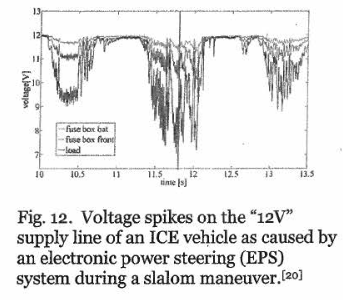
Notice how the 12V line is… erm… not 12V anymore? No computer chip can survive this level of voltage droop.
Further note: the designs here are OpAmps and ADCs, analog electronics. The location of the pedal on the accelerator is stored as a voltage at this point of the design. (“Before” the pedal information gets to the computer, it needs to be a physical voltage, if that makes any sense). The entire criticism here is on this analog / voltage level analysis, before the (traditional) computers are involved. (Arguably, this analog-circuitry is analog-computers. OpAmps are really cool and stuff, but these voltage-droops cause issues cause it changes the physical values that these things calculates)
Thank you for the explanation, it helped.
This should very clearly be addressed immediately, and… wow, what a huge bill (potentially) upcoming for Tesla.
At /r/RealTesla, we’ve been following this SUA problem for literally years.
A lot of us thought it was just the typical “stupid driver” pedal problem (Ex: Toyota’s SUA turned out to be just a bunch of people confusing the pedals). A lot of us thought it was due to one-pedal driving (training the Tesla drivers to confuse the pedals).
Turns out it was the hardware this whole time.
Given the level of detail, reverse engineering, and electrical knowledge in this .pdf, I really don’t see how Tesla survives this. They’re on the hook for many dozens of deaths already, if this .pdf is true.