
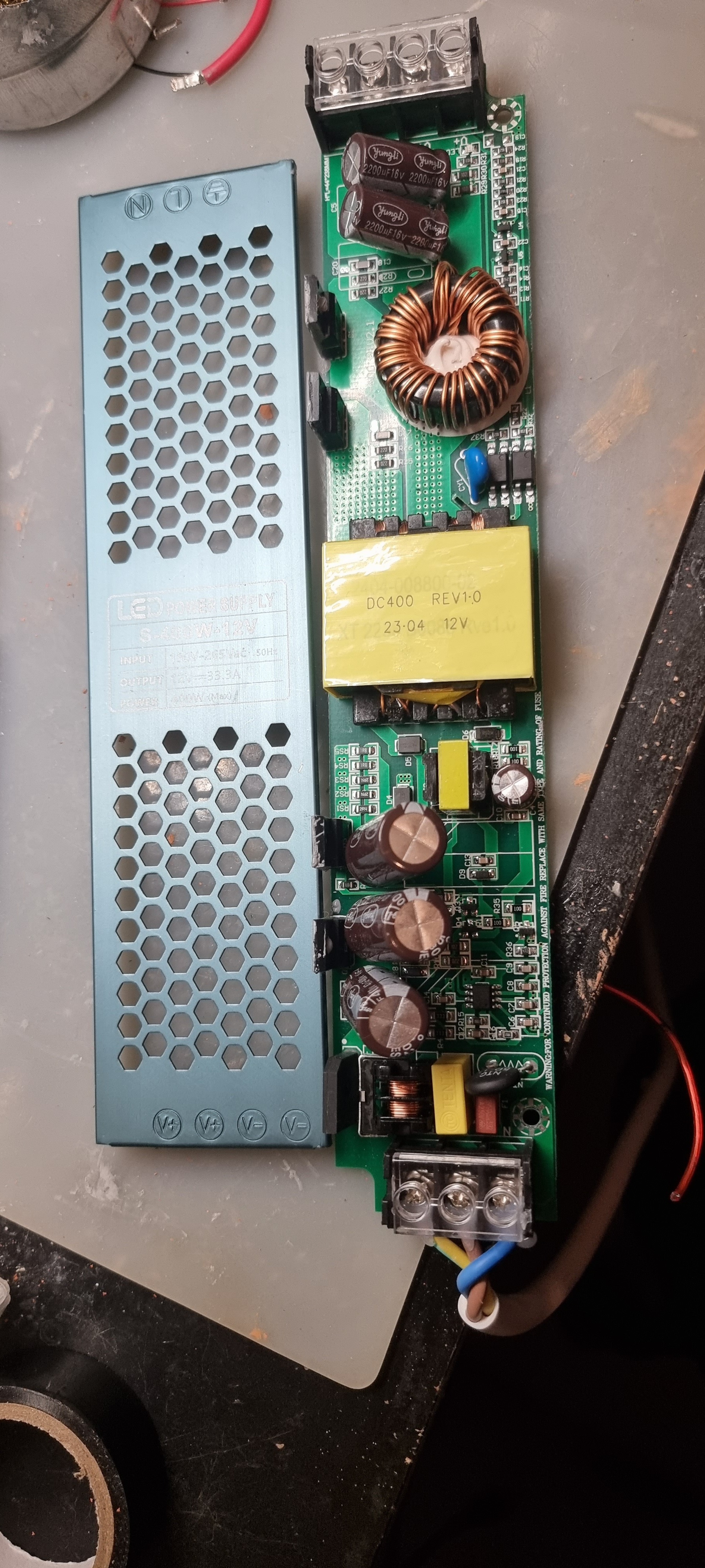
Does anyone recognise these power supplies? They’re cheap AliExpress led drivers and I want to change its output voltage to around 22V from 12V. I’ve read that the way to do this is to adjust the REF voltage on the IC that controls it. It’s a KA3845 but I don’t understand where that reference voltage is regulated. One voltage is feedback from the output where then other should be a reference.
What would be the best way to approach this? I can’t find any schematics on these boards unfortunately.
Thanks.
Considering there is what appears to be a fixed-stepdown 12 volt AC transformer on the line side of that board, I’d be surprised if you will change anything higher via IC’s.
This may be switch-regulated for rectification and line voltage correction but it definitely does not look modifiable.
That’s not a mains frequency transformer. Not enough steel. It’s a high-frequency all-switchmode supply.
However, that’s not to say you can simply adjust the feedback and have it safely deliver near twice the voltage. The secondary side diodes and capacitors probably won’t be up to it, or will have a very limited life.
The transformer does have a ratio, and the marking makes it clear that this is a specific part for the 12V model. How much leeway there is will depend on topology. Flyback are generally fairly flexible. Other types less so.
Starting with a 24V model and either adjusting the feedback resistors or adding a few diodes would be near trivial. Many will already have a potentiometer that provides that degree of adjustment. Starting with a 12V model is an uphill battle.
indeed it looks like a Royer oscillator in there (because there are transistors before AND after the transformer).
TO220 package diodes are pretty common in SMPS applications, so I’m not sure that’s a guarantee.
EDIT: Not sure what you’re getting at here? Royer doesn’t seem to need anything other than a rectifier on the secondary, and plenty of topologies use two power transistors on the primary.
The second smaller transformer below the main one does tend to suggest it could be a Royer, at least from my reading. I don’t see the extra switches needed for it to be a PFC stage.
There’s still a little SO-8 and optocouplers.
skipped reading the silkscreen … it says Q1 on the lowermost package but the other three are diodes. so could also be a forward converter or something similar.
Well there certainly is some regulation because attaching a load does not decrease the voltage by much. Increasing the voltage is indeed ambitious for the 12V model but lowering the voltage of the 12V model seems doable.