
I lost my electric fence tester, probably the pigs ate it. But I opened it once to resolder the earth wire and found it’s really just a voltage divider with resistors and leds, so I can probably rebuild with stuff I have. What resistor values though? 2k to 10k V run through the fence. If any of you good people have a diagram, a formula or an idea, please help.
You must log in or # to comment.
How was it like? Multiple leds which turned on depending on the voltage e.g. 1 led =2kV, 2 led = 4kV and so on?
Yes, multiple leds with more V = more LEDs
In the Wikipedia page there’s this formula
Just plug in values for the fence voltage and led. You can just set vswitch to 0 and Vled to 2V. It should be fairly insignificant compared to the fence voltage. It should be 10-20mA (0.01-0.02) to not kill the led.
The root of this is Ohms law: V=IR. Diodes cause a voltage drop rather than directly acting like a resistor which is why it’s subtracted from the input voltage.
Just put them in series. Make 2x, one in each direction to account for AC and DC
You could use something like this:
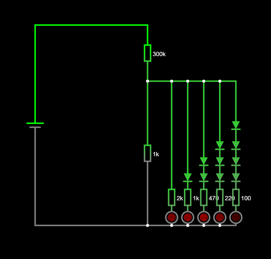
The diodes at least provide some steps - which just LEDs and resistors don’t. The dissipation in the main series resistors will be quite something, also. (You will probably need several resistors in series, if you use standard ones, with their standard voltage limits).