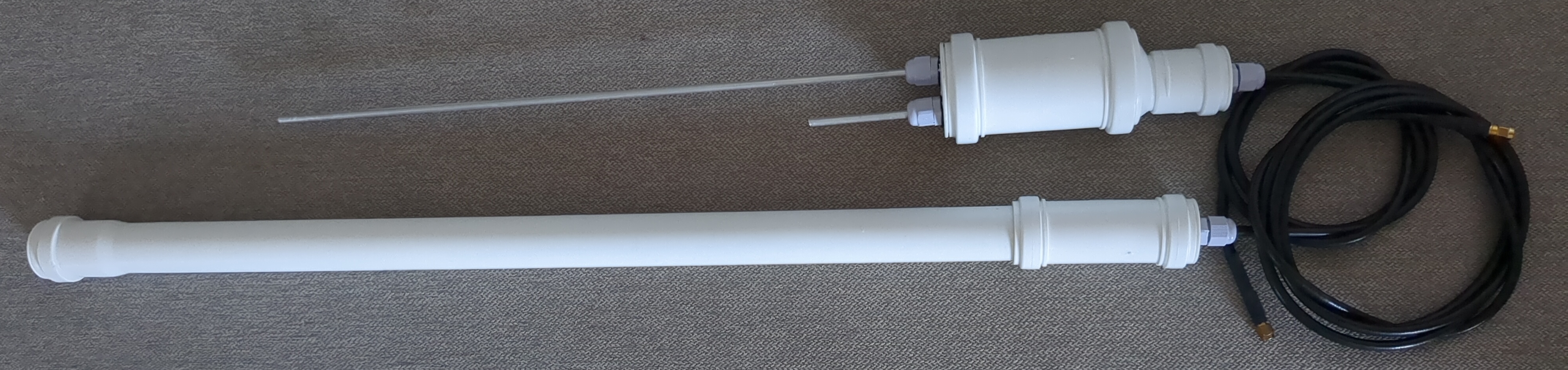
• 0 Posts
  • 563 Comments
Joined 10 months ago
cake
Cake day: March 31st, 2025

help-circle


  • Yeah this lower one looks better but still probably your capacitor value in loop is way off, try to find frequency where impedance is real (purely resistive; green line on smith chart crosses horizontal line in the middle) and work from there, then you’ll know whether to increase or decrease it. resonance is narrow so you might miss it. there’s a reason why magloops are made with variable capacitors (sometimes retuning is required due to changes in ex. humidity)

    how have you made your capacitor anyway?

    you can put some ferrite beads on your coax close to feedpoint in order to eliminate common mode currents. better yet, use a balun. this might help you in getting more reproductible results

    e: note how swr gets much higher when off resonance with properly calibrated nanovna. when measuring antenna with cable, you’re seeing loss in cable as a degree of lowered swr but only with high swr, because energy is lost in cable when it bounces around and never goes back to nanovna


  • i’ll add that in a way SWR chart is more resistant to misuse, because if nanovna is calibrated with wrong length of 50 ohm feedline, or without feedline at all, then smith chart will be rotated by angle depending on difference in length of that feedline, while SWR chart should look the same. for example, if real part of impedance at resonance is too low (ex. 20 ohm), and feedline is quarter wavelength different from what nanovna was calibrated with, then impedance will be still real but too high (ex. 125 ohm), while SWR chart should look the same (1:2.5 SWR minimum) (barring losses in feedline). (this works the same way as quarterwave long feedline impedance matching scheme). for different feedline length differences (non-multiple quarterwave) impedance will be complex at antenna resonance. this problem is avoided by calibrating nanovna with feedline


  • you can get away with very inefficient antennas on HF reception, so i wouldn’t take SDR reading very seriously. (atmospheric noise dominates all noise, so amplification will get you useful signal with amplifier not introducing significant noise on its own. reverse is true on vhf, and especially on uhf and up)

    resonance should happen no matter what power level. do you mean SWR 50 or 50 ohm? i’m not even sure if nanovna can measure SWR that high. it sounds like you have a short or open somewhere it shouldn’t be? you need to calibrate it after changing tested frequency range, have you done that? (calibration can be saved). at the vhf-ish frequencies, it would make sense that your loop becomes full wave or even larger. circular loop has impedance of some 100 ohms, but you have capacitor at the ends of it so it’s gonna be different

    with magloops, with set size of loop, tune is via changing capacitance, match is via changing position (closer or further from loop, tilt away from plane of loop), shape or size (cross sectional area) of feed loop, you can match it exactly this way. coax stub can be lossy, if it’s just 4W then probably not a problem but with higher powers check if it’s not overheating


  • i don’t think that a washed out royal surrounded by iranian version of cubans from miami would be very consequential, however if you compare scale of political persecution between pahlavi and islamic republic eras, this makes savak look downright humanitarian, and i don’t think he would be able to make situation worse either. if my calculator and judgement of sources is correct, then 43k dead protesters mean that islamic republic in two days outdid past 100 years of political repression, twice.

    also, islamic republic heavily exaggerated pahlavi’s brutality in their propaganda, especially early on. for example in constitution there’s mention of “60000 martyrs” but even their own revised estimates for 1979 casualties are over 20x lower